 WhatsApp: 11 97140-7653


Unitron
Total Control TCS 30
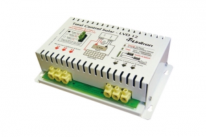
O Controlador TotalControl TCS 30, ligado entre um painel solar e uma bateria, funciona como um gerenciador de carga e descarga, mantendo a bateria dentro de condições ideais de funcionamento, assegurando assim longa vida útil. Controla carga/flutuação e também desliga a saída automaticamente, quando a bateria está com pouca carga, evitando que o usuário a descarregue totalmente, o que seria fatal para a vida útil da bateria.

Características
![]() Próprio para baterias chumbo-ácidas de 12 volts
Próprio para baterias chumbo-ácidas de 12 volts
![]() Controla carga e flutuação da bateria (painéis até 30A)
Controla carga e flutuação da bateria (painéis até 30A)
![]() Controla saída (até 30 ampères), desligando-a quando a tensão da bateria cai para 11,4V ± 2%, e religando-a quando a bateria, ao receber carga, atinge 12,7V ± 2%. Este sistema é conhecido pelas siglas CMT (Corte por Mínima Tensão) ou LVD (Low Voltage Disconnection)
Controla saída (até 30 ampères), desligando-a quando a tensão da bateria cai para 11,4V ± 2%, e religando-a quando a bateria, ao receber carga, atinge 12,7V ± 2%. Este sistema é conhecido pelas siglas CMT (Corte por Mínima Tensão) ou LVD (Low Voltage Disconnection)
![]() As funções de controle de carga e descarga são utilizáveis simultaneamente, nas potências máximas especificadas (painel até 30A + saída até 30A)
As funções de controle de carga e descarga são utilizáveis simultaneamente, nas potências máximas especificadas (painel até 30A + saída até 30A)
![]() Dispõe de fusível tipo automotivo, que proporciona proteção contra inversão de polaridade na ligação à bateria e contra sobrecarga ou curto-circuito na saída
Dispõe de fusível tipo automotivo, que proporciona proteção contra inversão de polaridade na ligação à bateria e contra sobrecarga ou curto-circuito na saída
![]() Opcionalmente, pode ser dotado de sensor para compensação da temperatura na bateria
Opcionalmente, pode ser dotado de sensor para compensação da temperatura na bateria
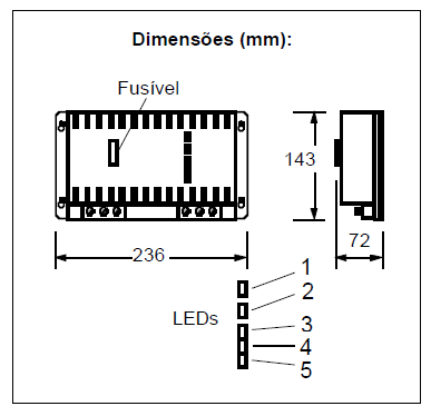
![]() É equipado com 5 LEDs que indicam:
É equipado com 5 LEDs que indicam:
- LED 1: Conexão invertida na bateria ou no painel solar
- LED 2: Condição de carga da bateria:
. Apagado, indica que a bateria não está recebendo carga, seja por falta de sol, fusível queimado,
bateria desconectada ou defeituosa, ou simplesmente por haver sido atingida a carga completa
. Aceso, bateria recebendo carga;
. Piscando, carga total sendo mantida (início do regime de flutuação). Quando a bateia se encontra
completamente carregada, os intervalos entre os lampejos do LED vão se tornando cada vez mais
espaçados, podendo chegar a um intervalo de minutos. A indicação deste LED é equivalente à de
um amperímetro de carga, isto é, ele acende somente quando a bateria está efetivamente recebendo
carga. O longo intervalo entre os lampejos no final da carga significa que a bateria está totalmente
carregada e não solicita mais corrente. Neste caso, os LEDs 3 a 5 estarão acesos.
- LEDs 3 a 5: Indicam a tensão da bateria:
. Os três LEDs acesos indicam tensão máxima (bateria totalmente carregada)
. Dois LEDs acesos indicam condição normal de tensão (faixa de utilização)
. Apenas um LED aceso: tensão baixa, final do período de autonomia
. Apagados: indicam saída desativada, seja por mínima tensão (LVD) ou por fusível queimado,
bateria desconectada, etc
Instalação:
1. Cobrir o painel solar durante a instalação, para que ele não gere eletricidade.
2. Ligar o painel solar ao TotalControl.
3. Instalar o TotalControl próximo à bateria (distância máxima = 2m, bitola mínima 10mm²): bornes B+ e B-
4. Para conexão ao painel (P+ e P-) e à saída (S+ e S-), utilizar a bitola de fiação conforme tabela abaixo.
5. Atenção à polaridade nas ligações: Usar cabos vermelhos para positivo e pretos para negativo.
6. Nunca unir entre si nenhum par de bornes, sejam os positivos ou os negativos.
7. A unidade deverá ficar abrigada da chuva e dos raios solares, em local com ventilação natural
(não instalar no interior de armários, caixas fechadas, etc.).
8. Apertar muito bem os parafusos dos conectores, evitando mau contato, pois isto acarreta mau
funcionamento e danos aos conectores.
9. Nunca utilize fusível de valor superior ao indicado: 30A
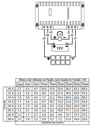
Obs.: A bitola máxima aceita pelos conectores é de 16mm². Para as instalações em distâncias longas, com bitola 25mm² ou superior, a instalação deverá ser executada por mão-de-obra especializada, utilizando-se conectores adaptadores de bitola.
| Especificações Elétricas | |
|
Tensão do Painel em Aberto |
Máx. 22,0Vcc |
|
Tensão de Entrada (Nominal) |
Para baterias chumbo-ácidas de 12 Vcc |
|
Corrente Máxima de Carga |
30A |
|
Corrente Máxima de Saída |
30A |
|
Tensão de Desligamento (LVD) |
11,4 ± 2% (*) |
|
Tensão de Religamento (LVR) |
12,7 V ± 2% (*) |
|
Tensão de Flutuação |
13,5 ± 0,1Vcc (*) |
| Fusível Tipo Automotivo |
30A |
|
Utilização Simultânea como Controlador de Carga e Descarga: Sim |
|
|
Indicação Visual da Condição de Carga da Bateria (Carregando/Flutuando): Sim |
|
|
Indicação Visual da Energia Armazenada na Bateria: Sim (Carga Total, Normal e Baixa) |
|
|
Indicação Visual da Condição da Saída (Habilitada/Desabilitada): Sim |
|
|
Indicação Visual de Conexão Invertida (Painel e Bateria): Sim |
|
|
Acessório Opcional: Sensor de Temperatura da Bateria, compensação -0,03V/ºC (*) |
|
(*) Estes valores podem ser alterados sob pedido
| Especificações Mecânicas | |
|
Material da Caixa |
Chapa de aço |
|
Acabamento |
Pintura a Pó Híbrida (Epoxi/Poliester) |
|
Conectores |
Parafusáveis, de Poliamida, para Condutores até 16mm² |
|
Pontos de Fixação |
Quatro, com formato "keyhole" |
|
Parafusos |
Inox |
|
Posição de Instalação |
Parafusado em Superfície Vertical |
|
Dimensões |
236 x 143 x 72mm |
|
Peso |
Aprox. 1,2 Kg |
|
Acesso Externo ao Fusível |
Sim |
|
Painel |
De Vinil, com inscrições indeléveis, |
|
Tropicalização |
Circuito Impresso Envernizado |
Especificações sujeitas a alterações sem aviso prévio - Folheto 656-L01-O05 R.2 - Edição 01/05 - Arq.: 656catp2.mcd
Solar XW MPPT60 150
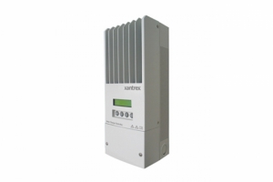
The Xantrex XW Solar Charge Controller (XW SCC) is a photovoltaic (PV) charge controller that tracks the electrical maximum power point of a PV array to deliver the maximum available current for charging batteries. When charging, the XW SCC regulates battery voltage and output current based on the amount of energy available from the PV array and state-of-charge of the battery.
The XW SCC can be used with 12, 24, 36, 48, and 60-volt DC battery systems and is able to charge a lower nominal-voltage battery from a higher nominal-voltage array. For example, the XW SCC can charge a 12-volt battery from a 36-volt array. This provides flexibility for installers to use longer wiring runs without compromising efficiency. The XW Solar Charge Controller can be installed (in single or multi-unit configurations) with Xantrex XW Hybrid Inverter/Charger(s) or can be used in other solar energy systems where a solar charge controller is needed.
The XW SCC incorporates a dynamic Maximum Power Point Tracking (MPPT) algorithm designed to maximize energy harvest from the PV array. The MPPT constantly adjusts the operating points of the array to ensure it stays on the maximum power point. It does not stop energy harvest to sweep the array like some other competing products. This feature is beneficial all sunlight conditions, especially in areas with fast moving cloud cover and quickly changing solar conditions.
EspecificStandard features of the Solar Charge Controller include:
![]() Maximum Power Point Tracking (MPPT) delivers maximum available power from PV array to battery bank
Maximum Power Point Tracking (MPPT) delivers maximum available power from PV array to battery bank
![]() Integrated PV ground-fault protection
Integrated PV ground-fault protection
![]() Ultra-reliable, convection-cooled design does not require a cooling fan − large, aluminum, die-cast heat-sink allows full output current up to 45°C without thermal derating
Ultra-reliable, convection-cooled design does not require a cooling fan − large, aluminum, die-cast heat-sink allows full output current up to 45°C without thermal derating
![]() Selectable two or three-stage charging algorithms with manual equalization to maximize system performance and improve battery life
Selectable two or three-stage charging algorithms with manual equalization to maximize system performance and improve battery life
![]() Configurable auxiliary output
Configurable auxiliary output
![]() Two-line, 16-character liquid crystal display (LCD) and four buttons for configuration and system monitoring
Two-line, 16-character liquid crystal display (LCD) and four buttons for configuration and system monitoring
![]() Input over-voltage and under-voltage protection, output over-current protection, and backfeed (reverse current) protection (warning and fault messages appear on LCD when unit shuts down as a protective measure)
Input over-voltage and under-voltage protection, output over-current protection, and backfeed (reverse current) protection (warning and fault messages appear on LCD when unit shuts down as a protective measure)
![]() Over-temperature protection and power derating when output power and ambient temperature are high
Over-temperature protection and power derating when output power and ambient temperature are high
![]() Battery Temperature Sensor (BTS) included − automatically provides temperature-compensated battery charging
Battery Temperature Sensor (BTS) included − automatically provides temperature-compensated battery charging
![]() Xanbus™-enabled network communications protocol (developed by Xantrex)
Xanbus™-enabled network communications protocol (developed by Xantrex)
![]() Communicates settings and activity to other Xanbus™-enabled devices, such as the XW Hybrid Inverter/Charger, the XW System Control Panel (XW SCP), XW Automatic Generator Start (XW AGS), and other XW Solar Charge Controllers.
Communicates settings and activity to other Xanbus™-enabled devices, such as the XW Hybrid Inverter/Charger, the XW System Control Panel (XW SCP), XW Automatic Generator Start (XW AGS), and other XW Solar Charge Controllers.
![]() Five-year warranty
Five-year warranty
| Electrical Specifications | |
|
Vmpp (V) Tensão no Ponto de Máxima Potência |
30,1 |
|
Maximum PV array voltage (operating) |
140 Vdc |
|
Maximum PV array open circuit voltage |
150 Vdc |
|
Array short-circuit current |
60 Adc maximum |
|
Maximum and minimum wire size in conduit |
#6 AWG to #14 AWG |
|
Total power consumption while operating |
2.5 W (tare) |
|
Charger regulation method: |
Three-stage (bulk, absorption, float) |
|
Two-stage (bulk, absorption) |
|
| Mechanical Specifications | |
|
Dimensions (H × W × D) |
14 ½ × 5 ¾ × 5 ½” (368 × 146 × 138 mm) |
|
Weight (Controller only) |
10.75 lb (4.8 kg) |
|
Weight (shipping) |
17.6 lb (8 kg) |
|
Shipping dimensions (H × W × D) |
19 × 9 × 9 ¾” (483 × 229 × 350 mm) |
|
Mounting |
Vertical wall mount |
|
Standard warranty |
Five years |
|
Part number |
865-1030 |
| Environmental Specifications | |
|
Enclosure type |
Indoor, ventilated, sheet metal chassis with 7/8”and 1” (22.22 mm and 27.76 mm) knockouts and aluminum heat-sink |
|
Operating temperature range (full power) |
-4 to 113 °F (-20 to +45 °C) |
|
Storage temperature |
-40 to 185 °F (-40 to +85 °C) |
|
Altitude limit (operating) |
Sea level to 15,000 feet (4572 m) @ 15 °C |
| Optional Accessories | |
|
XW System Control Panel |
865-1050 |
|
XW Automatic Generator Start |
865-1060 |
|
Network cables: |
|
|
3 feet (0.9 m) |
809-0935 |
|
5 feet (1.5 m) |
809-0936 |
|
7 feet (2.0 m) |
809-0937 |
|
10 feet (3.0 m) |
809-0938 |
|
14 feet (4.3 m) |
809-0939 |
|
25 feet (7.6 m) |
809-0940 |
|
50 feet (15.2 m) |
809-0941 |
| 75 feet (22.9 m) | 809-0942 |
| Network terminators: | Male (two per pack): 809-0901 |
| Female (two per pack): 809-0905 | |
| Regulatory Approvals |
|
Certified to UL 1741 1st Edition and to CSA 107.1-01 and carries the c(CSA)us mark |
Specifications subject to change without notice - For more information on the XW Series System please visit www.xantrex.com/xw
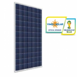
Módulos Fotovoltaicos Hanwha 235W e 250W
CARACTERÍSTICAS RELEVANTES:
- Qualidade garantida: 12 anos de garantia do produto e 25 anos de garantia de desempenho
- Expectativa de 25 anos para o rendimento (90% até 10 anos, 80% até 25 anos)
- Triagem por tolerância positiva: até 5W extras
- Maiores rendimentos específicos através de uma triagem por tolerância positiva
- Instalação simples e segura
- Produto certificado em conformidade com a norma IEC 61215 (2ª ed.)
- Classe de proteção II ou IEC 61730 Class A
- Certificações globais - CE, TUV, IEC, PV CYCLE, MCS/BABT
- Selo "A" INMETRO
Especificações
![]() Potências de 235 Wp e 250 Wp
Potências de 235 Wp e 250 Wp
![]() Classificação (escolha) -0/+5 Wp
Classificação (escolha) -0/+5 Wp
![]() Vidro temperado
Vidro temperado
![]() 60 células policristalinas de 156 x 156mm
60 células policristalinas de 156 x 156mm
![]() Moldura de liga de alumínio
Moldura de liga de alumínio
![]() Caixa de junção (IP67) com diodo by-pass
Caixa de junção (IP67) com diodo by-pass
![]() Revestimento traseiro à prova de intempéries
Revestimento traseiro à prova de intempéries
![]() Faixa de temperaturas de operação de -40 a +85ºC
Faixa de temperaturas de operação de -40 a +85ºC
![]() Certificações globais - CE, TUV, IEC, PV CYCLE, MCS/BABT
Certificações globais - CE, TUV, IEC, PV CYCLE, MCS/BABT
![]() Certificação brasileira - INMETRO Classe A
Certificação brasileira - INMETRO Classe A
![]() Certificação TUV de compatibilidade dos conectores com MC4
Certificação TUV de compatibilidade dos conectores com MC4
| Especificações Elétricas STC* | ||
|
Pmpp (Wp) Potência no Ponto de Máxima |
235 |
250 |
|
Vmpp (V) Tensão no Ponto de Máxima Potência |
30,1 |
30,4 |
|
Impp (A) Corrente no Ponto de Máxima Potência |
7,81 | 8,22 |
|
Voc (V) Tensão em Aberto |
36,8 |
37,2 |
|
Isc (A) Corrente de Curto-circuito |
8,44 |
8,74 |
|
Eficiência da Célula |
16,1 |
17,2 |
| Especificações Elétricas NOCT** | ||
|
Pmpp (W) Potência no Ponto de Máxima |
170 |
182 |
|
Vmpp (V) Tensão no Ponto de Máxima Potência |
27,3 |
27,7 |
|
Voc (V) Tensão em Aberto |
33,5 | 34,2 |
|
Isc (A) Corrente de Curto-circuito |
6,74 |
7,07 |
|
Impp(A) Corrente no Ponto de Máxima Potência |
6,23 |
6,58 |
|
% Eficiência |
16,1 |
17,2 |
*STC - Standard Test Conditions - Irradiação de 1000W/m² com espectro solar AM 1.5 e temperatura 25+-2ºC
**NOCT - Normal Operation Cell Temperature: nível de irradiação 800W/m², velocidade do vento 1m/s, operação em circuito aberto
Tolerâncias nas medições = +-3%
| Desempenho com Baixa Insolação | |
|
Intensidade |
Impp |
|
800 |
-20 |
|
600 |
-40 |
|
400 |
-60 |
|
200 |
-80 |
Valores a 25ºC e AM 1,5.
A perda de eficiência relativa com irradiação de 200W/m² é inferior a 5%
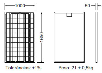
Dimensões (mm)
Nota relativa à montagem:
- Consultar o manual de montagem e operação
- Possibilidade de montagem horizontal e vertical
- Tensão máxima do sistema: 1 000 V
| Características Térmicas | |
|
Temperatura Normal de Operação |
45 +-3 ºC |
|
Coeficiente de Temperatura Pmpp |
-0,45% / ºK |
|
Coeficiente de Temperatura Voc |
-0,34% / ºK |
|
Coeficiente de Temperatura Isc |
-0,035% / ºK |
|
Faixa de Temperatura Ambiente |
-40 a +85ºC |
| Especificações Mecânicas | |
|
Dimensões: 1650 x 1000 x 45mm ± 1% |
Caixa de Junção: IP67 com diodo de derivação |
|
Peso: 21 ± 0,5kg |
Revestimento posterior resistente às intempéries |
|
Tipo: Policristalino, 60 células de 156 x 156mm |
Possibilidade de montagem horizontal ou vertical |
|
Vidro: Temperado |
Cabos de ligação: 4mm², comprimento 900mm, conectores Linyang LY0706-2, certificação TUV de compatibilidade com os conectores MC4
|
|
Moldura: Liga de alumínio |
|
|
|
Velocidade segura de impacto de granizo: 25mm a 23m/s |
Certificações

Especificações sujeitas a alterações sem aviso prévio Folheto HWA-L01-812 R.5 - Arq.: catalogo_hanwha_portugues_r5.mcd
Bosch Solar 265W Module c-Si M 60
Os nossos módulos solares cristalinos apresentam as seguintes vantagens:
![]() Produtos de alta qualidade garantida mediante a utilização dos melhores componentes segundo as normas europeias
Produtos de alta qualidade garantida mediante a utilização dos melhores componentes segundo as normas europeias
![]() Processo de produção excelente e estabilidade de longo prazo ao longo da cadeia de valor
Processo de produção excelente e estabilidade de longo prazo ao longo da cadeia de valor
![]() Maiores rendimentos específicos através de uma triagem por tolerância positiva
Maiores rendimentos específicos através de uma triagem por tolerância positiva
Nota relativa à montagem:
![]() Consultar o manual de montagem e operação em: www.bosch-solarenergy.com.pt/produtos
Consultar o manual de montagem e operação em: www.bosch-solarenergy.com.pt/produtos
![]() Possibilidade de montagem horizontal e vertical
Possibilidade de montagem horizontal e vertical
![]() Tensão máxima do sistema até 1 000 V
Tensão máxima do sistema até 1 000 V
![]() Gama de temperaturas operacionais –40 bis 85 °C
Gama de temperaturas operacionais –40 bis 85 °C
| Comportamento em condições de luminosidade fraca: | ||
|
Intensidade |
Vmpp |
Impp |
|
800 |
0,0 |
–20 |
|
600 |
0,0 |
–40 |
|
400 |
–0,18 |
–60 |
|
200 |
–2,36 |
–80 |
|
100 |
–5,45 |
–90 |
|
Os dados eléctricos são aplicáveis a 25 °C e AM 1,5. |
||
|
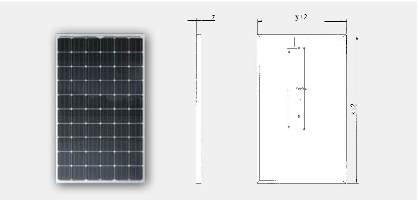
Comprimento |
Largura |
Altura da moldura [z] |
Peso | Tomada de ligação |
Tipo de tomada de ligação |
Cabo [l] |
Superfície do vidro frontal |
|
1 660,0 |
990,0 |
50,0 | 21 | IP65 | MC4 | –800 +1 200 |
Estruturada com revestimento antirreflexo |
| x, y, l em mm, ±2; z em mm, ±0,3; peso em kg ±0,5 | |||||||
| Módulo solar cristalino | |||||
|
Classes de potência |
255 Wp, 260 Wp, 265 Wp, 270 Wp |
||||
|
Gradação de potência |
–0/+4,99 Wp |
||||
|
Estrutura |
Laminado de vidro-película |
||||
|
Células |
60 células solares monocristalinas no formato de 156 mm x 156 mm | ||||
|
Carga mecânica admissível |
5 400 Pa de carga à superfície, 2 400 Pa de cargo do vento, segundo IEC 61215 (ensaio alargado) |
||||
| Características térmicas: | |
|
Coeficiente de |
TK |
|
Pmpp |
–0,44 |
|
Uoc |
–0,31 |
|
Isc |
0,031 |
| Características eléctricas em STC1: | ||||||
| Designação | Pmpp [Wp] |
Vmpp [V] |
Impp [A] |
Voc [V] |
Isc [A] |
Resistência à corrente inversa Ir [A] |
| 255 | 255 | 29,94 | 8,52 | 37,29 | 9,12 | 25 |
| 260 | 260 | 30,25 | 8,60 | 37,60 | 9,19 | 25 |
| 265 | 265 | 30,55 | 8,68 | 37,91 | 9,26 | 25 |
| 270 | 270 | 30,85 | 8,76 | 38,22 | 9,33 | 25 |
| Redução da eficiência do módulo em caso de diminuição da intensidade de radiação de 1 000 W/m2 para 200 W/m2 (a 25 °C): –0,32 % (absoluta) |
||||||
| Características eléctricas em NOCT1: | ||||
| Designação | Pmpp [W] |
Vmpp [V] |
Voc [V] |
Isc [A] |
| 255 | 185 | 27,52 | 30,06 | 7,35 |
| 260 | 189 | 27,79 | 30,31 | 7,40 |
| 265 | 193 | 28,07 | 30,56 | 7,46 |
| 270 | 196 | 28,35 | 30,81 | 7,52 |
| NOCT: Normal Operation Cell Temperature 48,4 °C: intensidade de radiação 800 W/m2, AM 1,5, temperatura 20 °C, velocidade do vento 1 m/s, tensão em circuito aberto |
||||
Dimensões 2:
1 Os parâmetros eléctricos reflectem valores médios típicos obtidos com base em dados de produção históricos. Não garantimos que estes dados estejam corretos para futuras cargas de produção.
2 Os desenhos não são apresentados à escala. Para obter medidas e tolerâncias pormenorizadas, ver acima.
As instruções do manual de montagem e operação da Bosch Solar Energy AG devem ser escrupulosamente respeitadas. A Bosch Solar Energy AG declina qualquer responsabilidade por danos em equipamentos utilizados com módulos solares da Bosch Solar Energy AG, nomeadamente nos casos em que não sejam respeitadas as fichas técnicas. Reservado o direito de proceder a modificações técnicas no âmbito da evolução do produto, assim como para correcção de falhas e erros.
Os nossos Certificados – Qualidade com Carta e Selo.
Os módulos Bosch Solar Energy, durante as diferentes fases de produção, passam por rigorosos testes de qualidade em conformidade com as normas internacionais.
Bosch Solar 240W Module c-Si M 60

Os nossos módulos solares cristalinos apresentam as seguintes vantagens:
![]() Produtos de alta qualidade garantida mediante a utilização dos melhores componentes segundo as normas europeias
Produtos de alta qualidade garantida mediante a utilização dos melhores componentes segundo as normas europeias
![]() Processo de produção excelente e estabilidade de longo prazo ao longo da cadeia de valor
Processo de produção excelente e estabilidade de longo prazo ao longo da cadeia de valor
![]() Maiores rendimentos específicos através de uma triagem por tolerância positiva
Maiores rendimentos específicos através de uma triagem por tolerância positiva
Nota relativa à montagem:
![]() Consultar o manual de montagem e operação em: www.bosch-solarenergy.com.pt/produtos
Consultar o manual de montagem e operação em: www.bosch-solarenergy.com.pt/produtos
![]() Possibilidade de montagem horizontal e vertical
Possibilidade de montagem horizontal e vertical
![]() Tensão máxima do sistema até 1 000 V
Tensão máxima do sistema até 1 000 V
![]() Gama de temperaturas operacionais –40 bis 85 °C
Gama de temperaturas operacionais –40 bis 85 °C
| Comportamento em condições de luminosidade fraca: | ||
|
Intensidade |
Vmpp |
Impp |
|
800 |
0,0 |
–20 |
|
600 |
0,0 |
–40 |
|
400 |
–0,18 |
–60 |
|
200 |
–2,36 |
–80 |
|
100 |
–5,45 |
–90 |
|
Os dados eléctricos são aplicáveis a 25 °C e AM 1,5. |
||
|
Comprimento |
Largura |
Altura da moldura [z] |
Peso | Tomada de ligação |
Tipo de tomada de ligação |
Cabo [l] |
Superfície do vidro frontal |
|
1 660,0 |
990,0 |
50,0 | 21 | IP65 | MC4 | –800 +1 200 |
Estruturada com revestimento antirreflexo |
| x, y, l em mm, ±2; z em mm, ±0,3; peso em kg ±0,5 | |||||||
| Módulo solar cristalino | |||||
|
Classes de potência |
255 Wp, 260 Wp, 265 Wp, 270 Wp |
||||
|
Gradação de potência |
–0/+4,99 Wp |
||||
|
Estrutura |
Laminado de vidro-película |
||||
|
Células |
60 células solares monocristalinas no formato de 156 mm x 156 mm | ||||
|
Carga mecânica admissível |
5 400 Pa de carga à superfície, 2 400 Pa de cargo do vento, segundo IEC 61215 (ensaio alargado) |
||||
| Características térmicas: | |
|
Coeficiente de |
TK |
|
Pmpp |
–0,44 |
|
Uoc |
–0,31 |
|
Isc |
0,031 |
| Características eléctricas em STC1: | ||||||
| Designação | Pmpp [Wp] |
Vmpp [V] |
Impp [A] |
Voc [V] |
Isc [A] |
Resistência à corrente inversa Ir [A] |
| 255 | 255 | 29,94 | 8,52 | 37,29 | 9,12 | 25 |
| 260 | 260 | 30,25 | 8,60 | 37,60 | 9,19 | 25 |
| 265 | 265 | 30,55 | 8,68 | 37,91 | 9,26 | 25 |
| 270 | 270 | 30,85 | 8,76 | 38,22 | 9,33 | 25 |
| Redução da eficiência do módulo em caso de diminuição da intensidade de radiação de 1 000 W/m2 para 200 W/m2 (a 25 °C): –0,32 % (absoluta) |
||||||
| Características eléctricas em NOCT1: | ||||
| Designação | Pmpp [W] |
Vmpp [V] |
Voc [V] |
Isc [A] |
| 255 | 185 | 27,52 | 30,06 | 7,35 |
| 260 | 189 | 27,79 | 30,31 | 7,40 |
| 265 | 193 | 28,07 | 30,56 | 7,46 |
| 270 | 196 | 28,35 | 30,81 | 7,52 |
| NOCT: Normal Operation Cell Temperature 48,4 °C: intensidade de radiação 800 W/m2, AM 1,5, temperatura 20 °C, velocidade do vento 1 m/s, tensão em circuito aberto |
||||
Dimensões 2:
1 Os parâmetros eléctricos reflectem valores médios típicos obtidos com base em dados de produção históricos. Não garantimos que estes dados estejam corretos para futuras cargas de produção.
2 Os desenhos não são apresentados à escala. Para obter medidas e tolerâncias pormenorizadas, ver acima.
As instruções do manual de montagem e operação da Bosch Solar Energy AG devem ser escrupulosamente respeitadas. A Bosch Solar Energy AG declina qualquer responsabilidade por danos em equipamentos utilizados com módulos solares da Bosch Solar Energy AG, nomeadamente nos casos em que não sejam respeitadas as fichas técnicas. Reservado o direito de proceder a modificações técnicas no âmbito da evolução do produto, assim como para correcção de falhas e erros.
Os nossos Certificados – Qualidade com Carta e Selo.
Os módulos Bosch Solar Energy, durante as diferentes fases de produção, passam por rigorosos testes de qualidade em conformidade com as normas internacionais.
Módulos Fotovoltaicos Yingli 55, 95, 140 e 250W
CARACTERÍSTICAS RELEVANTES:
- Qualidade garantida: 10 anos de garantia do produto e 25 anos de garantia de
desempenho, redução máxima de 20%
- Expectativa de 25 anos para o rendimento (90% até 10 anos, 80% até 25 anos)
- Maiores rendimentos específicos através de uma triagem por tolerância positiva
- Fábrica certificada pela TÜV Rheinland para ISO 9001:2008, ISO 14001:2004 e
BS OSHAS 18001:2007
- QUALIFICAÇÕES E CERTIFICADOS
IEC 61215, IEC 61730, UL 1703 e ULC 1703, UL Fire Safety Classe C, ISO
9001:2008, ISO 14001:2004, BS OSHAS 18001:2007, SA 8000, PV Cycle
- Selo "A" INMETRO
![]() Potências de 55 Wp a 250 Wp
Potências de 55 Wp a 250 Wp
![]() Classificação (escolha) -0/+5 Wp no modelo 250W
Classificação (escolha) -0/+5 Wp no modelo 250W
![]() Tecnologia policristalina, 36 células
Tecnologia policristalina, 36 células
![]() Tecnologia policristalina, 60 células, no modelo 250W
Tecnologia policristalina, 60 células, no modelo 250W
![]() Moldura de liga de alumínio anodizado, vidro temperado
Moldura de liga de alumínio anodizado, vidro temperado
![]() Revestimento traseiro à prova de intempéries
Revestimento traseiro à prova de intempéries
![]() Faixa de temperaturas de operação de -40 a +85ºC
Faixa de temperaturas de operação de -40 a +85ºC
| ESPECIFICAÇÕES TÉCNICAS | ||||
|
Condições padrões de Teste (STC*) |
|
|||
|
Potência Máxima (Pm) |
55 W |
95 W | 140 W | 250 W |
|
Tolerância |
-5%/+5% | -5%/+5% | -3%/+3% | -0%/+5% |
|
Voltagem de Máxima Potência (Vm) |
17,83 V |
18,18 V | 18,0 V | 30,4 V |
|
Corrente de Máxima Potência (Im) |
3,08 A |
5,23 A | 7,77 A | 8,24 A |
|
Voltagem de Circuito Aberto (Voc) |
22,07 V |
22,5 V | 22,5 V | 38,4 V |
|
Corrente de Curto-Circuito (Isc) |
3,28 A |
5,49 A | 8,4 A | 8,79 A |
|
Voltagem Máxima do Sistema |
50 V |
50 V | 1000 V | 1000 V |
|
Eficiência do Painel |
13,2% |
14,3% | 14,0% | 15,3% |
|
Coeficiente de Temperatura da Potência (Pm) |
-0,45 %/°C |
|||
|
Coeficiente de Temperatura da Corrente (Isc) |
0,06 A/°C |
|||
|
Coeficiente de Temperatura da Voltagem (Voc) |
-0,33 V/°C |
-0,33 V/°C | -0,37 V/°C | -0,33 V/°C |
|
Temp. Nominal de Operação de Célula (TNOC/NOCT) |
46±2°C |
|||
* STC/CPT: Irradiação de 1.000 W/m², Espectro de Massa de Ar 1.5 e Temperatura de Célula de 25°C
| Parâmetros Elétricos à Temperatura Nominal de Operação da Célula (NOCT) | |||||||||
|
Potência Máxima (Pm) |
44,55 W |
69,0 W | 113,4 W |
181,1 W |
|||||
|
Voltagem de Máxima Potência (Vm) |
16,43 V |
15,50 V | 16,59 V |
27,6 V |
|||||
|
Corrente de Máxima Potência (Im) |
2,47 A |
4,45 A | 6,26 A | 6,56 A | |||||
|
Voltagem de Circuito Aberto (Voc) |
20,08 V |
19,2 V | 20,28 V | 35,4 V | |||||
|
Corrente de Curto-Circuito (Isc) |
2,62 A |
5,16 A | 6,64 A | 7,12 A | |||||
Redução média relativa da eficiência de 5% a 200W/m², conforme EN 60904-1.
NOCT: Temperatura de operação do módulo em circuito aberto, sob irradiância de 800W/m², temperatura ambiente de
20°C e velocidade do vendo de 1m/s.
| Dimensões, Peso, Informações Mecânicas | ||||
| Dimensões do Módulo (mm) | 660 x 630 x 25 | 1010 x 660 x 25 | 1470 x 680 x 25 | 1650 x 990 x 40 |
| Grau de Proteção (IP) da Caixa de Junção | IP65 | |||
| Número de Células e Tipo | 36, Poli | 60, Poli | ||
| Peso do Módulo | 4,79 kg | 7,65 kg | 11,8 kg | 19,1 kg |
| Vidro, Tipo e Espessura (mm) | Alta Transmissividade, Baixo Ferro, Vidro Temperado 3,2mm | |||
| Condições Operacionais | ||||
| Faixa de Temperatura de Trabalho | -40°C a 85°C | |||
| Carga Estática Máxima, frente (vento e neve) | 2400 Pa | 5400 Pa | ||
| Carga Estática Máxima, trás (vento e neve) | 2400 Pa | 2400 Pa | ||
| Máximo Impacto de Granizo (diâmetro/velocidade) | 25mm / 23m/s | |||

Especificações sujeitas a alterações sem aviso prévio Catalogo YII-L01-815 R.1 - Arq.: catalogo_yingli_portugues_r1.mcd
FREEDOM SW 2000 Sine Wave Inverter/Charger
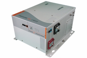
PURE POWER. TRUE VALUE.
The Freedom SW 2000 inverter/charger features pure sine wave output and power factor corrected multi-stage charging to meet power needs of today’s sensitive and sophisticated electronics. The Freedom SW 2000 offers premium performance and hard-to-match pricing in one package. It provides 2000 watts of continuous sine wave power to operate commonly used AC-powered electronics such as plasma television sets, microwaves, entertainment systems, computers, printers, power tools, mini refrigerator and much more. It packs a powerful 100 A charger and is available with an optional GFCI.
Application
![]() Designed for a variety of mobile applications such as commercial, emergency and recreational vehicles,
Designed for a variety of mobile applications such as commercial, emergency and recreational vehicles,
marine vessels, construction and military equipment.
Product Features
![]() Pure sine wave output to operate sensitive electronics
Pure sine wave output to operate sensitive electronics
![]() Built-in transfer switch automatically transfers between inverter power and incoming AC power
Built-in transfer switch automatically transfers between inverter power and incoming AC power
![]() Power factor corrected multi-stage charger for fast, efficient charging
Power factor corrected multi-stage charger for fast, efficient charging
![]() Temperature compensated charging for all climate conditions
Temperature compensated charging for all climate conditions
![]() Wide operating temperature range: 32°F to 122°F (0°C to 50°C)
Wide operating temperature range: 32°F to 122°F (0°C to 50°C)
![]() Ignition lockout prevents unnecessary battery drain when the alternator is not providing power*
Ignition lockout prevents unnecessary battery drain when the alternator is not providing power*
![]() Adjustable low battery voltage cut-off
Adjustable low battery voltage cut-off
![]() Conformal coated circuit boards for humid environments
Conformal coated circuit boards for humid environments
![]() On/off remote control panel with 25’ cable included (Part# 808-9002)
On/off remote control panel with 25’ cable included (Part# 808-9002)
![]() Easy to install and easy to use
Easy to install and easy to use
![]() Optional GFCI (part# 808-9003)
Optional GFCI (part# 808-9003)
![]() Meets CSA, UL458 (with marine supplement), ABYC and FCC Part 15, Class B requirements
Meets CSA, UL458 (with marine supplement), ABYC and FCC Part 15, Class B requirements
*When used with On/off remote panel
Protection Features
![]() Battery over-voltage and under-voltage protection
Battery over-voltage and under-voltage protection
![]() Over-temperature shutdown
Over-temperature shutdown
![]() Automatic overload protection
Automatic overload protection
![]() Short-circuit protection
Short-circuit protection
![]() Ground-fault protection on units with GFCI option
Ground-fault protection on units with GFCI option
Also Available
![]() FREEDOM SW 3000 Sine Wave Inverter/Charger (Part# 815-3000)
FREEDOM SW 3000 Sine Wave Inverter/Charger (Part# 815-3000)
| Electrical Specifications - Inverter | |
|
Output power (continuous at 30°C) |
2000 W |
|
Surge rating (10 seconds) |
4000 W |
|
Output frequency |
60 Hz ± 0.2 Hz |
|
Output voltage |
120 Vac |
|
Output wave form |
Pure sine wave |
|
Optimal efficiency |
90% |
|
No-load power draw (inverting) |
2 Adc |
|
Input DC voltage range |
11 - 15 Vdc |
|
AC connections |
Single |
|
Low battery voltage cut-off |
10.5 V, 11.8 V (selectable) |
| Electrical Specifications - Charger | |||
|
Output current |
100 A |
||
|
Output voltage |
12 Vdc |
||
|
Output voltage range |
10.0 - 15.5 Vdc | ||
|
Charge control |
3 stage with manual equalize | ||
|
Charge temperature compensation |
Battery temperature sensor (included) | ||
|
Optimal Efficiency |
> 85% | ||
|
AC input power factor (full power) |
> 0.98 | ||
|
Input current (for 100/150 A charging) |
15.8 Aac | ||
|
Input AC voltage |
120 Vac | ||
|
Input AC voltage range |
95 - 140 Vac | ||
| Dead battery charge | > 8.5 Vdc | ||
| General Specifications | |
| Compatible battery types | Flooded / gel / AGM / |
| Transfer relay rating | 30 A, 120 Vac |
| Transfer time (AC to inverter and inverter to AC) | 20 ms |
| Optimal operating temperature range | - 4°F to 122°F (- 20°C to 50°C) |
| Storage ambient temperature range | - 4°F to 167°F (- 20°C to 75°C) |
| Optimal operating temperature range | 0°C to 50°C |
| Unit dimensions (H x W x L) | 7.75 x 13.5 x 15.25” (19.7 x 34.3 x 38.7 cm) |
| Unit weight | 27.5 kg (60.5 lbs) |
| Warranty | 2 years |
| Master carton quantity | 1 |
| Master carton dimensions | 11.8 x 17.1 x 20.5” (30 x 43.5 x 52.2 cm) |
| Master carton weight | 30 kg (66 lbs) |
| Part Number | 815-2000 |
| Accessories | |
| Freedom SW on/off remote panel | Part# 808-9002 - INCLUDED |
| Battery Temperature Sensor | Part# 808-0232-01 - INCLUDED |
| GFCI Option | Part# 808-9003 - SOLD SEPARATELY |
| Drip shield | Part# 808-9004 - SOLD SEPARATELY |
| Regulatory & Environmental Compliance | |
| ETL certified to CSA 107.1, UL458 with marine supplement**, FCC Class B | |
*When used with the Drip Shield. Drip Shield sold separately. Note: Specifications subject to change without notic
© 2010 Xantrex Technology Inc. All rights reserved. Xantrex and Smart choice for power are trademarks of Xantrex International, registered in the U.S. and other countries.
FREEDOM SW 3000 Sine Wave Inverter/Charger

PURE POWER. TRUE VALUE.
The Freedom SW 3000 inverter/charger is packed with features and it is one of the most advanced inverter/chargers in the market today. It features premium sine wave output with high surge capability and temperature compensated, power factor corrected, multi-stage charging to meet power needs of
demanding loads including inductive motor loads.
The Freedom SW 3000 inverter/charger provides 3000 watts of utility grade AC power to operate commonly used AC-powered electronics such as plasma television sets, microwaves, entertainment systems, computers, printers, power tools, refrigerators and much more.
Application
![]() Designed for a variety of mobile applications such as commercial, emergency and recreational vehicles,
Designed for a variety of mobile applications such as commercial, emergency and recreational vehicles,
marine vessels, construction and military equipment.
Product Features
![]() Pure sine wave output to operate sensitive electronics
Pure sine wave output to operate sensitive electronics
![]() Advanced configuration options for customized applications
Advanced configuration options for customized applications
![]() Built-in transfer switch automatically transfers between inverter power and incoming AC power
Built-in transfer switch automatically transfers between inverter power and incoming AC power
![]() Power factor corrected multi-stage charger for fast, efficient charging
Power factor corrected multi-stage charger for fast, efficient charging
![]() Temperature compensated charging for all climate conditions
Temperature compensated charging for all climate conditions
![]() Ignition lockout prevents unnecessary battery drain when the alternator is not providing power*
Ignition lockout prevents unnecessary battery drain when the alternator is not providing power*
![]() Wide operating temperature range: -4°F to 140°F (-20°C to 60°C)
Wide operating temperature range: -4°F to 140°F (-20°C to 60°C)
![]() Conformal coated circuit boards for humid environments
Conformal coated circuit boards for humid environments
![]() Dual input / Dual output AC interface
Dual input / Dual output AC interface
![]() Compatible with the Xantrex Automatic Generator Start** (Part# 809-0915)
Compatible with the Xantrex Automatic Generator Start** (Part# 809-0915)
![]() On/off remote control panel with 25’ cable included (Part# 808-9002)
On/off remote control panel with 25’ cable included (Part# 808-9002)
![]() Field upgradeable firmware
Field upgradeable firmware
![]() Meets CSA, UL458 (with marine supplement), ABYC and FCC Part 15, Class B requirements
Meets CSA, UL458 (with marine supplement), ABYC and FCC Part 15, Class B requirements
*When used with the remote panel
**Sold separately
Protection Features
![]() Battery over-voltage and under-voltage protection
Battery over-voltage and under-voltage protection
![]() Over-temperature shutdown
Over-temperature shutdown
![]() Automatic overload protection
Automatic overload protection
![]() Short-circuit protection
Short-circuit protection
![]() Integrated, resettable AC breakers
Integrated, resettable AC breakers
Also Available: Freedom SW 2000 Sine Wave Inverter/Charger (Part# 815-2000)
| Electrical Specifications - Inverter | |
|
Output power (continuous at 25°C) |
3000 W |
|
Surge rating (10 seconds) |
6000 W |
|
Output frequency |
60 Hz +/- 0.2 Hz |
|
Output voltage |
120 Vac |
|
Output wave form |
Pure sine wave |
|
Optimal efficiency |
90% |
|
No-load power draw (inverting) |
3 Adc |
|
Input DC voltage range |
10 - 16 Vdc |
|
AC connections |
Split phase in / dual out, Dual in / dual out |
| Electrical Specifications - Charger | |||
|
Output current |
150 A |
||
|
Output voltage |
12 Vdc |
||
|
Output voltage range |
5 - 16 Vdc | ||
|
Charge control |
3 stage with manual equalize | ||
|
Charge temperature compensation |
Remote battery sensor (included) | ||
|
Optmial Efficiency |
> 85% | ||
|
AC input power factor |
0.95 | ||
|
Input current (for 150 A charging) |
22 A rms nominal | ||
|
Input AC voltage |
120 Vac | ||
|
Input AC voltage range |
95 - 140 Vac | ||
| Dead battery charge | > 5 Vdc | ||
| General Specifications | |
| Compatible battery types | Flooded / gel / AGM |
| Transfer relay rating | 2 legs at 30 A each |
| Transfer time (AC to inverter and inverter to AC) | < 20 ms |
| Optimal operating temperature range | - 4°F to 140°F (- 20°C to 60°C) |
| Storage ambient temperature range | - 40°F to 185°F (- 40°C to 85°C) |
| Unit Dimensions (H x W x L) | 7.75 x 13.5 x 15.25” (19.7 x 34.3 x 38.7 cm) |
| Unit weight | 33.5 kg (73.7 lbs) |
| Warranty | 2 yea |
| Master carton quantity | 1 |
| Master carton dimensions (H x W x L) | 11.8 x 17.1 x 20.5” (30 x 43.5 x 52.2 cm) |
| Master carton weight | 35 kg (77 lbs) |
| Part Number | 815-3000 |
| Accessories | |
| Freedom SW on/off remote panel | Part# 808-2009 - INCLUDED |
| Battery temperature sensor | Part# 808-0946 - INCLUDED |
| Automatic Generator Start (AGS) | Part# 809-0915 - SOLD SEPARATELY |
| System control panel (SCP) | Part# 809-0910 - SOLD SEPARATELY |
| 25’ network cable for system control panel | Part# 809-0940 - SOLD SEPARATELY |
| 75’ network cable for system control panel | Part# 809-0942 - SOLD SEPARATELY |
| Drip shield | Part# 808-9004 - SOLD SEPARATELY |
| Regulatory & Environmental Compliance | |
| ETL certified to CSA 107.1, UL458 with marine supplement**, FCC Part 15, Class B | |
**When used with the Drip Shield. Drip Shield sold separately.
Note: Specifications subject to change without notice
© 2009 Xantrex Technology Inc. All rights reserved. Xantrex and Smart choice for power are trademarks of Xantrex International, registered in the U.S. and other countries.
INVERSOR XW
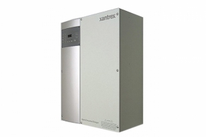
Xantrex™ brings the next generation of inverter/charger to market, with the XW Hybrid Inverter/Charger, the heart of the XW System. The XW Hybrid Inverter/Charger (XW) is a true sine wave, 120/240-volt AC, split-phase, inverter/charger that incorporates a DC to AC inverter, a battery charger, and an AC auto-transfer switch. It is the foundation for battery- based residential and commercial applications up to 18 kilowatts (kW). Capable of being grid-interactive or grid-independent, the XW can operate with generators and renewable energy sources to provide full-time or backup power.
Designed with consultation and input from industry experts, dealers, and installers, the XW sets a new standard for battery-based inverter/chargers. Integrating the best features available in the market, innovative new features by Xantrex and balance-of-systems components, the XW Hybrid Inverter/Charger’s design makes installation quicker and easier. The XW offers high efficiency and unprecedented surge capacity to maximize the owner’s return on investment. No other inverter/charger looks or performs like the XW.
Product Features
![]() True sine wave output
True sine wave output
![]() 120/240 volt AC spilt-phase operation
120/240 volt AC spilt-phase operation
![]() Dual AC inputs
Dual AC inputs
![]() Integrated design to minimize external balance-of-system components
Integrated design to minimize external balance-of-system components
![]() XanBus™-enabled network communication
XanBus™-enabled network communication
![]() Certified to UL1741 and CSA for utility-interactive applications
Certified to UL1741 and CSA for utility-interactive applications
![]() Unprecedented surge capacity
Unprecedented surge capacity
![]() Efficient, power factor corrected, high-current, multistage battery charging
Efficient, power factor corrected, high-current, multistage battery charging
Optional Accessories
| Item | Part Number |
| - XW Power Distribution Panel | 865-1015 |
|
- XW Connection Kit for Second Inverter |
865-1020 |
|
- XW Conduit Box |
865-1025 |
|
- XW Solar Charge Controller |
865-1030 |
|
- XW System Control Panel |
865-1050 |
|
- XW Automatic Generator Start |
865-1060 |
For more information on the XW System please visit www.xantrex.com/xw
| Electrical Specifications | |||
|
Model |
XW6048-120/240-60 |
XW4548-120/240-60 |
XW4024-120/240-60 |
|
Continuous output power |
6,000 W |
4500 W |
4000 W |
|
Surge rating (10 seconds |
12,000 W |
9000 W |
8000 W |
|
Surge current |
L-N: 105 Arms (7 sec) |
L-L: 52.5 Arms (7 sec) |
L-N: 75 Arms (20 sec) |
|
Waveform |
True sine wave |
True sine wave |
True sine wave |
|
Low-load efficiency |
95% |
95% |
95% |
|
Idle consumption - search mode |
< 8 W |
< 8 W |
< 8 W |
|
AC connections |
AC1 (Grid), AC2 (Generator |
AC1 (Grid), AC2 (Generator |
AC1 (Grid), AC2 (Generator) |
|
AC voltage |
120/240 Vac split-phase |
120/240 Vac split-phase |
120/240 Vac split-phase |
|
AC input breaker |
60 A two-pole |
60 A two-pole |
60 A two-pole |
|
Utility interactive |
Yes |
Yes |
Yes |
|
CEC weighted efficiency |
92.5% |
93% |
91% |
|
CEC power rating |
5752 W |
4500 W |
4000 W |
|
AC input voltage range (bypass/charge mode) |
L-N: 80 - 150 Vac (120 V nominal); L-L: 160 - 270 Vac (240 V nominal) |
||
|
AC input frequency range (bypass/charge mode) |
55 - 65 Hz (default); 44 - 70 Hz (allowable) |
||
|
AC1 voltage range – Sell mode |
L-N: 108 - 130 +/- 1.5 Vac; L-L: 214 - 260 +/- 3.0 Vac |
||
|
AC1 frequency range – Sell mode |
59.4 - 60.4 +/- 0.05 Hz |
||
|
AC output voltage |
L-N: 120 Vac +/- 3%; L-L: 240 Vac +/- 3% |
||
|
AC output frequency |
60.0 +/-0.1 Hz |
||
|
DC current at rated power |
130 A | 96 A | 178 A |
|
Total harmonic distortion |
< 5% | ||
|
Automatic transfer relay |
60 A | ||
|
Typical transfer time |
8 ms | ||
|
DC input voltage (nominal) |
50.4 Vdc | 50.4 Vdc | 25.2 Vdc |
|
DC input voltage range |
44 - 64 Vdc | 44 - 64 Vdc | 22 - 32 Vdc |
|
Maximum continuous charge rate |
100 A | 85 A | 150 A |
|
Efficiency at maximum charge rate |
89.4% | 90.2% | 85.8% |
|
Power factor corrected charging |
0.98 | 0.98 | 0.98 |
|
Emissions |
FCC Class B | FCC Class B | FCC Class B |
|
Multiple-unit configurations |
Up to three parallel units in 120/240-volt split-phase configuration | ||
|
Auxiliary relay output |
0-12 Vdc, maximum 250 mA DC | ||
|
Non-volatile memory |
Yes | Yes | Yes |
|
System network |
Xanbus™ (publish-subscribe network, no need for hubs or special cards) | ||
| Mechanical Specifications | |||
|
Mounting |
Wall mount, backplate included |
||
|
Inverter dimensions (H x W x D) |
23 x 16 x 9” (580 x 410 x 230 mm) |
||
|
Inverter weight |
125 lb (57 kg) |
115 lb (52 kg) |
115 lb (52 kg) |
|
Shipping dimensions |
28 x 22 ¼ x 10 ½” (711 x 565 x 267 mm) | ||
|
Shipping weight |
132 lb (60 kg) |
122 lb (55 kg) |
122 lb (55 kg) |
|
Display panel |
Status LEDs indicate AC In status, faults/warnings, equalize mode, battery level. Three-character display indicates output power or charge current, fault/warning codes. On/Off and equalize buttons |
||
|
Battery temperature sensor |
Included |
Included |
Included |
|
Standard warranty |
Five years (10 years optional) |
Five years (10 years optional) |
Five years (10 years optional) |
| Environmental Specifications | |
| Enclosure type | NEMA Type 1 – Indoor (sensitive electronic components sealed inside enclosure) |
| Operational temperature range | -13 to 158 °F (-25 to 70 °C) |
| Accessories | |
| Remote display | Optional XW System Control Panel monitors and configures all devices connected to Xanbus™ Network |
| Generator support | Optional XW Automatic Generator Start module connects to Xanbus™ Network. Automatically activates generator to recharge depleted battery bank or assist inverter with heavy loads |
| Power distribution & panel conduit boxes | Optional balance-of-systems components for NEC compliant installations, includes pre-wired AC and DC circuit breakers, bus bars and multiple knockouts for conduit and additional breakers |
| Regulatory Approvals | |
| UL 1741 1st Edition: 2005 Version CSA 107.1-01 | |
Specifications subject to change without notice
© 2008 Xantrex Technology Inc. All rights reserved. Xantrex, Xanbus, and Smart choice for power are trademarks or registered trademarks of Xantrex International. Printed in Canada.
RS Sine Wave Inverter/Charger 2000 and 3000
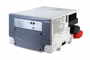
Powerful, easy-to-use sine wave inverter/chargers featuring an upgradeable design and built-in networking.
RS Inverter/Chargers are simply the most advanced and easy to use on the market. Premium sine wave output and a high surge capability will power appliances and electronic devices, including microwaves, entertainment systems, coffee makers, power tools, and lights.
A power factor corrected three-stage charger provides long battery life by recharging batteries more quickly, while using less AC power. The stress-tested, UL458 design delivers reliable power in demanding conditions. An aluminum chassis and high-temperature operation guarantee long-term
trouble-free performance. They also meet strict electromagnetic interference standards designed to minimize interference with radios and other onboard electronics.
RS Inverter/Chargers are Xanbus Enabled, so it’s easy to connect network-enabled accessories as well as share power status and diagnostic information with other devices. Xanbus makes power management less complex, while intelligently making the best use of available power resources. The inverter/chargers and accessories have built-in flash memory so their software can be upgraded to take advantage of new features and system enhancements.
Product Features
![]() 2000 watt inverter/5000 watt surge rating and 3000 watt inverter/7500 watt surge rating
2000 watt inverter/5000 watt surge rating and 3000 watt inverter/7500 watt surge rating
![]() Sine wave output to power sensitive appliances and electronics
Sine wave output to power sensitive appliances and electronics
![]() 120/150A power factor corrected multi-stage charger for fast, efficient charging
120/150A power factor corrected multi-stage charger for fast, efficient charging
![]() Full power inverter and charger output to 122ºF (50ºC)
Full power inverter and charger output to 122ºF (50ºC)
![]() Split phase or dual in-phase inputs offers flexible use of available AC power
Split phase or dual in-phase inputs offers flexible use of available AC power
![]() Advanced diagnostics and field upgradeable software
Advanced diagnostics and field upgradeable software
![]() Meets UL458 standards and FCC Class B regulations
Meets UL458 standards and FCC Class B regulations
![]() Xanbus Enabled
Xanbus Enabled
Protection Features
![]() Battery over voltage and under voltage protection
Battery over voltage and under voltage protection
![]() Over temperature protection
Over temperature protection
![]() Automatic overload protection
Automatic overload protection
![]() Short circuit protection
Short circuit protection
| Electrical Specifications – Inverter | ||
| Model | RS2000 | RS3000 |
| Output power (continuous) | 2000 W | 3000 W |
|
Surge rating (5 second) |
5000 W (42 A) |
7500 W (60 A) |
|
Output voltage |
120 VAC |
120 VAC |
|
Output frequency |
60 Hz + / -0.05% (crystal controlled) |
60 Hz + / -0.05% (crystal controlled) |
|
Output waveform |
Sine wave <3% THD |
Sine wave <3% THD |
|
Peak efficiency |
>92% |
>90% |
|
Efficiency (full load) |
>87% |
>85% |
|
No load power draw (load sense) |
<14.4 W |
<20 W |
|
AC connections |
Single / Dual* |
Split phase in / dual out, Dual in / dual out |
|
AC transfer capacity |
30 A (single in) |
2 legs at 50 A (split phase in), 2 legs at 30 A (dual in) |
|
Transfer time |
20 ms (typical) |
20 ms (typical) |
*See options under ‘Part Numbers’
| Electrical Specifications – Charger | ||
|
Output current |
120 ADC |
180 ADC |
|
Battery voltage (nominal) |
12 VDC |
12 VDC |
|
Battery voltage range |
10.0 – 15.5 VDC |
10.0 – 15.5 VDC |
|
Charge control |
3 stage with manual equalize |
3 stage with manual equalize |
|
Charge temperature compensation |
Remote battery sensor (included) |
Remote battery sensor (included) |
|
Efficiency |
85% typical |
85% typical |
|
AC input power factor |
0.95 |
0.95 |
|
Input current (maximum charge rate 150 A) |
17 A RMS (120 A) |
22 A RMS (150 A) |
|
AC input voltage |
120 VAC nominal |
120 VAC nominal |
|
AC input voltage range |
90 – 135 VAC |
90 – 135 VAC |
|
Compatible battery types |
Wet / Gel / AGM |
Wet / Gel / AGM |
| General | ||
|
Operating temperature range |
-4ºF – 122ºF (-20ºC – 50ºC) |
-4ºF – 122ºF (-20ºC – 50ºC) |
|
Storage temperature range |
-40ºF – 122ºF (-40ºC – 50ºC) |
-40ºF – 122ºF (-40ºC – 50ºC) |
|
Dimensions (H x W x D) |
8.17 x 13.25 x 16” (208 x 336 x 406 mm) |
8.17 x 13.25 x 16” (208 x 336 x 406 mm) |
|
Weight |
68.0 lbs. (30.9 kg) |
75.0 lbs. (34.01kg) |
|
Warranty |
3 years |
3 years |
|
Part Numbers |
Single in / Single out |
809-2000 |
|
Accessories |
System Control Panel |
809-0910 |
| Regulatory Approvals |
| CSA/NRTL certified to CSA 107.1, UL 458 FCC Class B/Industry Canada Class B |
Note: Specifications subject to change without notice
© 2005 Xantrex Technology Inc. All rights reserved. Xantrex is a registered trademark of Xantrex International. Printed in Canada
Catálogos e Manuais
Produtos

Newsletters
![]()
Unitron Engenharia, Indústria & Comércio Ltda.
Rua Balsa, 601 - Vila Arcádia
CEP: 02910-000 - São Paulo - SP
Tel: (11) 3931-4744
Whatsapp: (11) 97140-7653
Redes Sociais
 |
facebook.com/unitron |
 |
twitter.com/unitron |
 |
youtube.com/unitron |